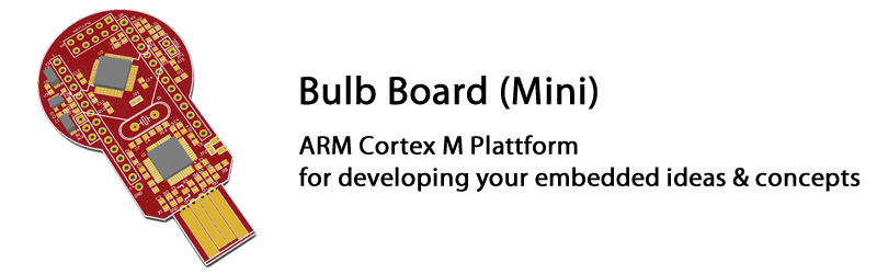
Develop own embedded ideas
The Bulb Board (Mini) is a platform to help you to quickly check ideas without needing to buy or build special hardware. It runs out of the box, USB-powered and brings its own debugger. Simply start writing software and connect whatever your idea needs to the MCU pins. Additional concepts can be added as add-on board or via the Multicon connector.Start with bulb board: Start simple and grow into the application.
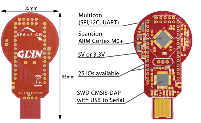
The Bulb Board Mini has everything on-board required for an easy start:
Microcontroller USB to SWD (serial wire debug)USB to Serial Converter USB to Serial Converter (with virtual COM port for the PC) Multicon Connector (SPI, I2C or UART) Pin-Headers in 2.54mm Grid 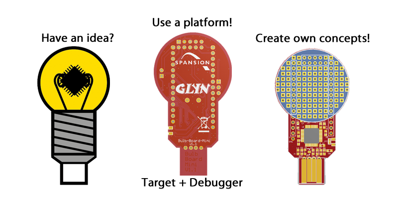
The Arduino Question
There are so many shields available for Arduino, so why is Bulb Board not compatible to Arduino shield boards?In general Arduino is a good concept and in the meanwhile became a standard for the embedded hobby market. Unfortunately the boards are very big and not in 2.54mm grid. Even if the connector would be the same, the software for Arduino shields boards must be ported and Arduino shields couldn't be used directly.
Flexible evaluation board for flexible microcontroller
The Bulb Board was designed for the Spansion Flexible Microcontrollers (FM Series) based on ARM Cortex M core. The Bulb Board Mini uses an ARM Cortex M0+ MCU.Features
Microcontroller: Spansion S6E1A12B0AGP2 ARM Cortex M0+ 88KByte Flash 6KByte SRAM 1x Multicon (I2C, SPI or UART) USB to UART converter USB debugger (CMSIS-DAP) 25 pins usable 2 user LEDs available
Overview
Hardware
Schematic
schematic_BULB-BOARD-MINI_V11.PDF The microcontroller
[ Source: Spansion Website www.spansion.com ]Direct link to product site: S6E1A12B0AGP2
Jumper Settings
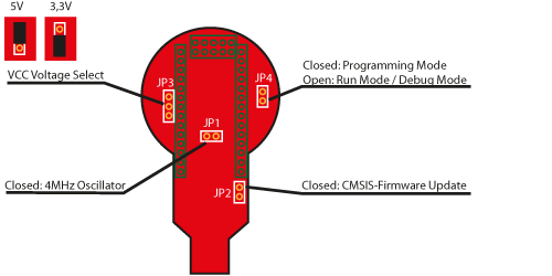
Pin Headers
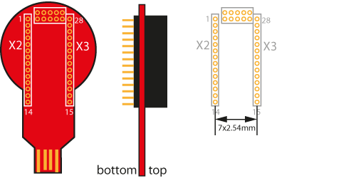
Pin Header X2
Pin Description 1 P3A/RTO00_0/TIOA0_1/AIN0_3/SUBOUT_2/RTCCO_2/INT03_0/SCK0_2 2 P3B/RTO01_0/TIOA1_1/BIN0_3/SOT0_2/INT04_0/SCS31_2 3 P3C/RTO02_0/TIOA2_1/ZIN0_3/SIN0_2/INT05_0/SCS30_2 4 P3D/RTO03_0/TIOA3_1/INT06_0/AIN0_0/SCK3_2 5 P3E/RTO04_0/TIOA0_0/BIN0_0/SOT3_2/INT15_0 6 P3F/RTO05_0/TIOA1_0/ZIN0_0/SIN3_2 7 P46/X0A 8 P47/X1A 9 INITX 10 PE0/ADTG_1/DTTI0X_1/INT02_2 11 MD0 12 PE2/X0 13 PE3/X1 14 5V Pin Header X3
Pin Description 15 GND 16 P11/AN01/SIN1_1/INT02_1/FRCK0_2/IC02_0 17 P12/AN02/SOT1_1/IC00_2/INT01_1 18 P13/AN03/SCK1_1/SUBOUT_1/IC01_2/RTCCO_1/INT00_1 19 P23/AN06/SCK0_0/TIOA2_0/IC02_1/AIN0_1/INT04_1 20 P22/AN07/SOT0_0/TIOB2_0/IC03_1/ZIN0_1/INT05_1 21 P21/SIN0_0/INT06_1/TIOB1_1/IC01_1/BIN0_1/FRCK0_0 22 P01/SWCLK 23 P03/SWDIO 24 P04/SCK3_0/INT03_2/TIOB0_1/IGTRG0_1 25 P0F/NMIX/SUBOUT_0/CROUT_1/RTCCO_0 26 P61/SOT3_0/TIOB2_2/DTTI0X_2/SCS11_2 27 P60/SIN3_0/TIOA2_2/INT15_1/IC00_0/IGTRG0_0/SCS10_2 28 VCC Multicon
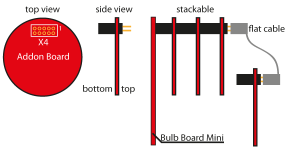
The multicon connector offers a stackable solution for adding concept boards connected via SPI, I2C or UART.
For SPI up to 3 devices can be connected (3 chip selects possible) For UART up to 4 devices can be connected (4 chip selects possible) For I2C up to 127 devices can be connected
Multicon Schematic
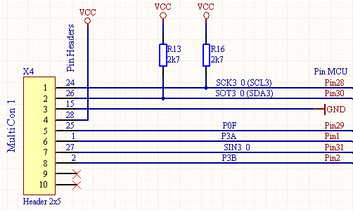
Pin description
Pin X2/X3 Description 1 24 (X3) SCL or SPI Clock (MFS3_0) 2 26 (X3) SDA or SPI TX or UART TX (MFS3_0) 3 15 (X3) GND 4 28 (X3) VCC 5 25 (X3) P0F/NMIX/SUBOUT_0/CROUT_1/RTCCO_0 6 1 (X2) P3A/RTO00_0/TIOA0_1/AIN0_3/SUBOUT_2/RTCCO_2/INT03_0/SCK0_2 7 27 (X3) SPI RX or UART RX 8 2 (X2) P3B/RTO01_0/TIOA1_1/BIN0_3/SOT0_2/INT04_0/SCS31_2 9 NC 10 NC USB to Debug / UART
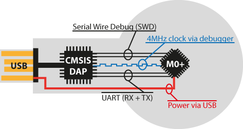
Pin X2/X3 Description 12 (X2) 4MHz clock, JP1 must be set (MCU PE2/X0) 20 (X3) UART 0 TX (MCU) (SOT0_0) 21 (X3) UART 0 RX (MCU) (SIN0_0) 22 (X3) JTAG Serial Wire Debug Clock (SWCLK) 23 (X3) JTAG Serial Wire Debug IO (SWDIO) Tutorial: How to use CMSIS-DAP debugger
Downloads
Examples
Example Size Description s6e1a1_bulb-board-mini-demo_v10.zip 181 KB Example with board support package, dimming LEDs s6e1a1-series-201402.zip 131 KB S6E1A1 Series Template / Sample Program s6e1xx-pdl-v10.zip 12,3 MB FM0+ Peripheral Driver Library s6e1xx_uart_hexdwl_bootloader-v10.zip 502 KB UART Bootloader based on HEXDWL protocol incl. PC command line tool s6e1a1_bulb-board-mini-demo-hexdwl-required_v10.zip 502 KB Example with board support package, dimming LEDs ready to use with HEXDWL bootloader (linked to 0x4000) Tutorials
Tutorial Size Description readme_cmsisdap.pdf 505 KB How to use CMSIS-DAP debugger readme_iar.pdf 784 KB How to use IAR EWARM with Spansion templates readme_keil.pdf 859 KB How to use Keil uVision with Spansion templates Documentation
Documentation Size Description schematic_BULB-BOARD-MINI_V11.pdf 394 KB Schematic Bulb Board Mini S6E1A1_DS710-00001-E.pdf 1,2 MB Datasheet Spansion FM0+ S6E1A1 Series S6E1A1_MN710-00001.pdf 4,1 MB Peripheral Manual: System, Clock, LVD, DMA, GPIO, etc. S6E1A1_MN710-00002.pdf 4,2 MB Peripheral Manual: Timer Part S6E1A1_MN710-00003.pdf 1,2 MB Peripheral Manual: Analog Macro Part S6E1A1_MN710-00004.pdf 5 MB Peripheral Manual: Communication Macro Part S6E1A1_MN710-00005.pdf 358 KB Flash Programming Manual Driver
Driver Size Description driverinstaller.exe 700 KB Driver for CMSIS-DAP and programming Utilities
Utilities Size Description N/A N/A KB Serial Flash Programming Tool SerialPortViewerAndTerminalV56.exe 1,2 MB Serial Port Viewer & Terminal Toolchain (IDE)
IAR Embedded Workbench
Download latest version from IAR WebsiteEWARM 30-day Evaluation Version
http://supp.iar.com/Download/SW/?item=EWARM-EVALEWARM 32K Kickstart Version
http://supp.iar.com/Download/SW/?item=EWARM-KS32ARM Keil uVision
Download latest version from KEIL WebsiteEvalualtion Version
https://www.keil.com/demo/eval/arm.htm
(Registration required)